How Do Photonic Interconnects Work?
What is the Light Source for Photonic Interconnects?
For a Photonic Integrated Circuit (PIC) to function, it requires a light source. While some PICs can integrate lasers directly on-chip, the most common and scalable approach for high-bandwidth applications—particularly in AI interconnects—is to use external lasers.
Why Use External Lasers?
Integrating high-power, stable lasers off-chip offers several key advantages:
- Thermal Management: Lasers run more efficiently and with greater wavelength stability when kept cool. Moving them off the PIC and away from hot XPUs or switch ASICs (which can reach up to 120 °C) allows them to run in a controlled environment—typically much below 120 °C—ensuring stable output power and wavelength.
- Reliability and Serviceability: External lasers can be field-replaceable, allowing failed or degraded sources to be swapped without disturbing the PIC or the entire module—improving uptime and maintainability in large systems.
- Power Efficiency and Scalability: A single external laser can feed multiple PICs or channels, reducing the number of lasers needed, lowering total power consumption, and simplifying thermal and optical power management at scale.
How Is Data Traffic Converted Into Light in a Photonic Integrated Circuit?
In a PIC, a continuous laser beam, injected into the chip through an optical fiber, and a high-speed electrical signal, carrying data from a processor like a GPU or switch, come together to create an optical data stream:
1. Laser Light Injection
A continuous beam of laser light is generated by an external laser source. This light travels through a precision-aligned optical fiber, which is physically coupled to the PIC using one of two basic approaches:
- Permanently attached or detachable fiber using Fiber Array Units (FAU): FAUs provide precise passive alignment between the fiber and the chip and are used in both permanent and detachable coupling schemes. Detachability, is enabled by additional components such as a glass ferrule or plug with a receptacle, allowing the fiber to be removed or replaced without disturbing the PIC.
- Coupling methods:
- Grating couplers use etched surface gratings to bend light from the fiber into the chip at near-vertical angles, simplifying alignment.
- Edge couplers inject light horizontally through the chip facet, offering lower loss and higher coupling efficiency but requiring tighter alignment.
The light that enters the PIC through the fiber is directed by internal waveguides to a modulator.
Learn More: Scaling Up AI with Optical Interconnects
2. Electrical Data Input from SerDes
At the same time, high-speed electrical signals, typically SerDes (Serializer/De-Serializer) from a switch or GPU, arrive at the PIC’s electrical interface. These signals carry the raw analog data to the modulator receiving the light from the laser.
3. Modulation — Where Light and Data Merge
At the heart of the PIC, the continuous laser light and the electrical data stream intersect at a specialized component called a Micro-Ring Modulator (MRM) or Mach-Zehnder Modulator (MZM).
- The modulator uses the electrical signal to control properties of the laser light — such as its amplitude, phase, or frequency — effectively encoding data onto the light.
- This process transforms a continuous laser beam into a high-speed stream of optical bits that can travel long distances with low loss.
How Do Photonic Integrated Circuits Route Light?
Optical routing within PICs is achieved by manipulating light paths on the chip. This is analogous to how switches direct traffic in an electronic network, but here, the data “traffic” is light. The laser light enters through an optical fiber attached to the edge of the PIC. It is then modulated and carried with specialized photonic components and exits the PIC through another attached fiber.
What Specialized Components are Used in Photonic Integrated Circuits?
- Waveguides: These are the fundamental “optical highways” — microscopic channels on the chip that guide injected light with minimal loss, similar to how fiber optic cables work, but at chip scale.
- Modulators: These components are responsible for converting electronic signals into optical ones by modulating the injected laser light. They precisely alter the light’s intensity or phase to encode data.
- Detectors: At the receiving end, photodetectors convert the modulated light signals back into electrical signals so they can be processed by conventional electronic systems.
- Through Silicon Vias (TSV): Vertical metal connections drilled and filled from the bottom of the PIC that carry signals and power through the silicon.
Learn More: Lightmatter’s Photonics Innovations
What is Wavelength Division Multiplexing (WDM)?
In wavelength-division multiplexing (WDM), different wavelengths (colors) of light are combined onto a single optical fiber and later split at the receiving end to recover the individual data streams. Each wavelength carries its own independent signal, allowing multiple channels of data to be transmitted in parallel over the same fiber. Individual wavelengths don’t directly interact with the other wavelengths even when they’re traveling together or exist in the same space simultaneously.
How is WDM Used in Fiber Optic Connectivity?
- To combine multiple parallel data streams moving in the same direction, increasing bandwidth without adding more fibers.
- To simultaneously transmit and receive on different wavelengths over the same fiber, enabling full-duplex (Tx/Rx) communication with fewer physical links.
This makes WDM a fundamental technology for scaling bandwidth in modern data centers and for AI interconnects.
What Photonic Components Enable Wavelength Division Multiplexing (WDM)?
In wavelength-division multiplexing (WDM), the combining and splitting of different wavelengths (colors) of light is handled by multiplexers (mux) and demultiplexers (demux).
On a photonic chip, these functions are typically performed by:
- Arrayed Waveguide Gratings (AWGs): Use interference across multiple waveguide paths to combine or separate wavelengths with high precision.
- Micro-Ring Resonators: Selectively couple light at specific wavelengths in or out of a waveguide.
- Diffraction Gratings (e.g., Echelle Gratings): Act like a prism to spatially separate or combine wavelengths.
- MMI Couplers and Thin-Film Filters: Used in simpler or discrete implementations.
These components allow multiple independent data streams—each on a different wavelength—to travel over a single optical waveguide or fiber.
What Role Do Microring Modulators (MRMs) Play in Wavelength Division Multiplexing (WDM)?
- Each microring modulator (MRM) is tuned to a specific wavelength and modulates only that single wavelength of light. This allows multiple MRMs, each operating at a different wavelength (or “color”), to independently carry separate data streams in parallel—a fundamental enabler of Wavelength Division Multiplexing (WDM).
- MRMs also act as wavelength-selective filters, enabling precise add/drop multiplexing. When a resonant wavelength passes through the bus waveguide, the corresponding microring can “drop” that wavelength to another output or “add” a new data stream at that wavelength into the waveguide. By combining many MRMs, each tuned to a unique wavelength, multiple independent channels can be multiplexed onto a single waveguide and transmitted out through a fiber, dramatically increasing total bandwidth
What are the Different Kinds of Wavelength Division Multiplexing (WDM)?
CWDM (Coarse Wavelength Division Multiplexing)
CWDM is like a highway with a few wide lanes. It uses a small number of widely spaced wavelengths to transmit data.
How it Works: In current high-volume CPO applications, such as the 400G FR4 standard, CWDM uses 4 wavelengths per fiber. The “coarse” spacing makes the components simpler and less expensive to manufacture, which is why it’s a common choice for shorter-reach, high-volume interconnects.
DWDM (Dense Wavelength Division Multiplexing)
DWDM is like a superhighway with many narrow lanes packed closely together. It uses a much larger number of tightly spaced wavelengths.
In the context of photonic interconnects, DWDM systems typically use up to 16 wavelengths per fiber, with very tight spacing. This enables a massive increase in bandwidth density, crucial for the massive data movement required by AI and machine learning systems.
WDM Directionality: Most existing WDM solutions for photonic interconnects are unidirectional, requiring one fiber for transmit and a separate one for receive. However, this is changing with recent innovations.
Advanced Bi-Directionality: A recent DWDM breakthrough has enabled 16 bidirectional wavelengths on a single fiber, where 8 wavelengths transmit data in one direction and 8 wavelengths transmit data in the other direction. This represents an eight-fold increase over existing CWDM photonic interconnects that support two wavelengths (one transmitted in each direction) on a single fiber.
Learn More: Doubling Down: World’s First 16-λ Single Fiber Bidirectional Link for AI
What Are the Benefits of Wavelength Division Multiplexing (WDM)?
Wavelength-division multiplexing (WDM) dramatically increases bandwidth by using different wavelengths (colors) of light to carry multiple data channels over the same optical fiber or waveguide, enabling:
- Massive data capacity over a single fiber, without additional cabling, through parallel transmission of independent data streams
- Efficient use of existing infrastructure, reducing cost and complexity
- Scalability, as more wavelengths (and thus more channels) can be added over time without physically changing the fiber
WDM turns a single optical path into a multi-lane data highway, making it essential for scaling AI interconnects in high-performance data centers.
What is Bidirectional (BiDi) Wavelength Division Multiplexing (WDM) and Why Does it Matter?
Bidirectional WDM (BiDi) is a specific implementation of WDM that enables full-duplex communication over a single optical fiber by transmitting and receiving on different wavelengths. Unlike traditional duplex links that require two fibers (one for each direction), BiDi allows both directions to share the same fiber, effectively cutting fiber usage in half.
Key Benefit: BiDi WDM Increases Radix, or Port Density
- Doubling Port Capacity: If each duplex connection normally requires two fibers, the same fiber plant can support twice as many ports at the same speed with BiDi.
- Higher Per-Port Speeds: BiDi also enables maintaining the same number of ports while increasing per-port bandwidth without exceeding fiber or panel limits.
By reducing the fiber requirement for full-duplex communication, BiDi WDM makes it easier to scale both port count and bandwidth simultaneously, which is critical in AI and high-performance data center networks where fiber infrastructure can be a limiting factor.
What Is Optical Circuit Switching (OCS) in AI Interconnect?
Optical Circuit Switching (OCS) is a network-level application of photonic switching, designed to establish dedicated optical paths (circuits) between endpoints for the duration of a connection. Unlike packet-switched electronic networks, where data is divided into packets and routed dynamically, OCS maintains a fixed optical path once the connection is configured.
In AI interconnects, OCS enables the creation of high-bandwidth, reconfigurable communication fabrics, which are particularly useful for orchestrating large-scale data transfers between accelerators or memory banks.
Key Features of Optical Circuit Switching (OCS)
- Reconfigurability: Optical circuits can be dynamically re-routed to accommodate changes in traffic patterns or to bypass failed components.
- Scalability: By establishing direct optical paths between endpoints, OCS can connect many nodes in a data center without relying solely on electrical switches.
- Switch-Centric Architecture: The core of OCS is the optical switch, which can be realized on-chip or off-chip:
- On-Chip Switches
- Mach-Zehnder Interferometers (MZIs): Split a light signal into two paths and recombine them with a controlled phase shift to route the signal to the desired output.
- Ring Resonators: Use resonance effects to selectively direct specific wavelengths, enabling compact, wavelength-selective switching.
- Off-Chip Switches
- Micro-Electro-Mechanical Systems (MEMS): Robotic mirrors or actuators that physically redirect light beams between fibers or optical ports.
- Other Free-Space Optical Elements: Configurable mirrors or lenses that enable large-scale optical circuit fabrics outside the chip.
- On-Chip Switches
Considerations in AI Interconnects
- Training Required: When a circuit is reconfigured, the transmitter and receiver may need retraining to align the optical path.
- Insertion Losses: Optical switches introduce losses, which can sometimes offset the efficiency gains from avoiding repeated optical-electrical-optical conversions.
- Latency: OCS is generally not optimized for low-latency packet delivery; reconfiguration times are in the millisecond to second range, making it more suitable for sustained, large data transfers rather than fine-grained, latency-sensitive traffic.
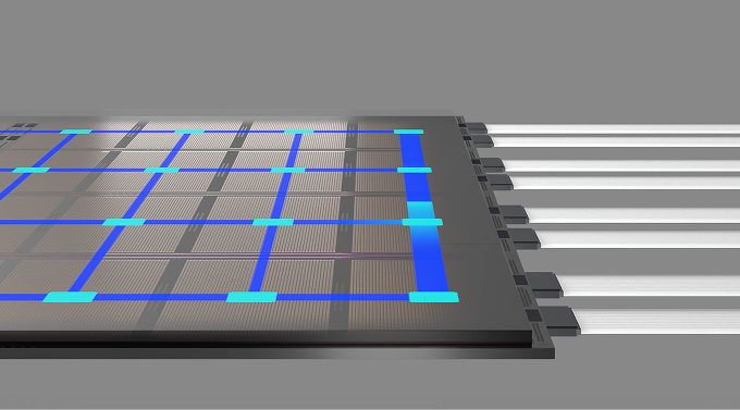
How Does Optical Circuit Switching Work in a Photonic Integrated Circuit?
Within a photonic integrated circuit (PIC), waveguides are laid out in a grid or network. By placing an MZI at each intersection point where two waveguides cross, the light from one waveguide can be selectively routed to the other. The MZI acts as a tiny, electro-optically controlled traffic director that can switch the light signal from the “bar” state (straight through) to the “cross” state (turning 90 degrees). By controlling a series of these MZIs, a continuous, low-loss optical path is established from a source to a destination, effectively creating a dedicated “lane” of light through the network. This is the essence of OCS in a PIC.